Introduction
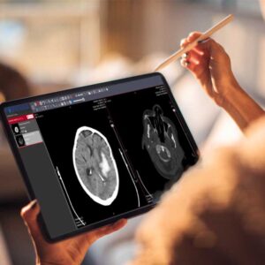
MPR/MIP workflows are foundational for extracting clinically actionable insight from volumetric imaging such as CT and MRI. MPR (Multiplanar Reconstruction) generates anatomically meaningful cross-sections from a 3D volume, while MIP (Maximum Intensity Projection) collapses a user-defined slab of voxels to emphasize high-intensity structures—most notably contrast-filled vessels and calcifications. This article reviews the technical underpinnings of MPR/MIP, then details how these capabilities are realized in XEUS, a DICOM viewer designed for fast, reproducible interpretation. The emphasis is on accurate geometry, robust resampling, and practical, clinician-oriented controls. (Keyword focus: MPR/MIP.)
1) Technical Foundations of MPR
MPR computes a resampled 2D plane through a 3D lattice of voxels in patient coordinates. Correct geometry and sampling are essential for diagnostic fidelity.
Patient space and DICOM geometry.
- ImageOrientationPatient (0020,0037) provides two orthonormal in-plane direction vectors (row, column) in patient space (commonly LPS).
- ImagePositionPatient (0020,0032) gives the 3D origin of the slice.
- PixelSpacing (0028,0030) and SliceThickness (0018,0050) define sampling intervals.
- CT voxel intensities are mapped to Hounsfield Units (HU) via RescaleSlope (0028,1053) and RescaleIntercept (0028,1052).
Isotropic resampling. Volumes acquired with anisotropic spacing (e.g., 0.6×0.6×2.5 mm) yield jagged (“stair-step”) obliques. Pre-resampling to isotropic voxels (e.g., 0.6 mm³) markedly improves edge fidelity, true orthogonality of measurements, and stability of thin-slice MPR/MIP.
Interpolation strategy. When mapping the target plane back into the source lattice, interpolation governs noise, sharpness, and metric accuracy:
- Nearest-neighbor is fast but aliasing-prone; rarely acceptable diagnostically.
- Trilinear (piecewise linear in 3D) is the clinical workhorse—smooth and inexpensive.
- Cubic (e.g., Catmull-Rom) preserves edges better at higher cost; helpful for small vessels and bony detail.
Arbitrary and curved planes. Beyond orthogonal axial/coronal/sagittal, oblique planes align with anatomy (e.g., acetabular plane, aortic root). Curved Planar Reformation (CPR) follows a user-defined centerline through a tubular structure (coronary, biliary, tracheobronchial tree) and re-slices orthogonally along that path, “unfolding” the lumen for continuous assessment.
Quantification on correct planes. Linear and angular measurements should be performed on planes orthogonal to a structure’s principal axis to avoid over- or under-estimation from oblique incidence.
2) Technical Foundations of MIP/MinIP/AvIP
MIP forms each output pixel by taking the maximum intensity along a ray through a slab of thickness T in the projection direction: I_out(x,y) = max_{z in [z0, z0+T]} I(x,y,z). This emphasizes high-HU voxels (iodinated blood, calcium, bone), revealing vessel continuity and stenoses.
- MinIP replaces the maximum with a minimum, highlighting low-attenuation structures (airways, emphysema).
- AvIP (Average Intensity Projection) averages intensities within the slab, suppressing noise and conveying parenchymal signal trends when MIP/MinIP would saturate.
Key parameters.
- Slab thickness & position: Thin slabs (3–10 mm) minimize superimposition; thicker slabs improve vessel continuity but increase overlap. Scrolling the slab provides a 3D survey in 2D.
- Window/Level or transfer function: Proper contrast mapping is decisive—vascular windows for CTA/MRA, lung windows for airway MinIP.
- Acquisition physics: Blooming around stents/calcifications in CT can exaggerate stenosis on MIP; careful windowing and, when available, de-blooming filters help. Partial-volume effects increase with slab thickness.
3) MPR/MIP Workflow in XEUS (Control Model and UI Semantics)
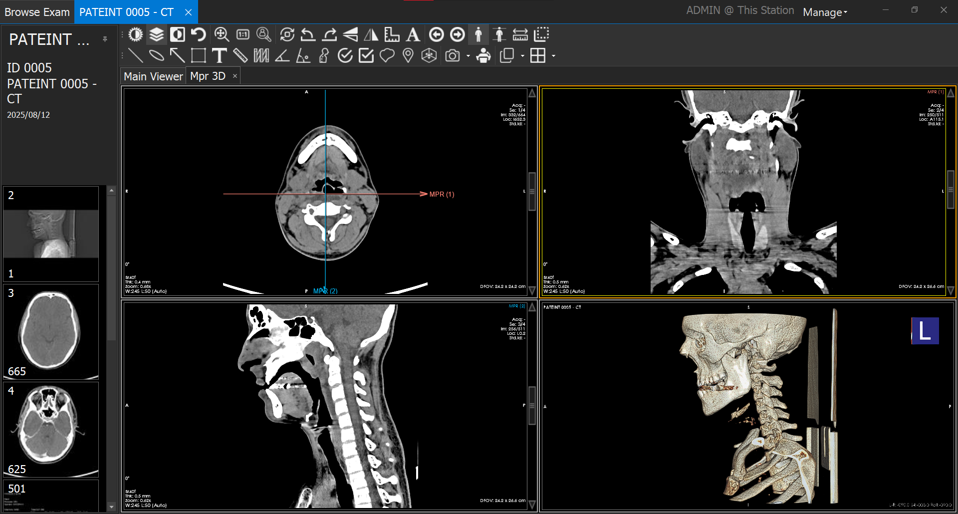
XEUS implements a consistent, reference-line–driven MPR/MIP workspace to keep geometry explicit and reproducible.
Layout and reference behavior.
- The top-left image box always shows the source series from which MPR was initiated.
- The two other image boxes are each controlled by their own MPR line drawn on a separate reference image. Lines are color-coded and labeled to ensure unambiguous identification.
- Each MPR line defines the orientation of its generated image—analogous to cross-reference lines across display sets.
- Every generated image extends from the top to the bottom of the reference image stack.
- One end of each MPR line carries an arrowhead that encodes orientation; by convention, the arrow points from the left side to the right side of the generated images.
Starting MPR in XEUS.
- Select and add the series you intend to reformat.
- Click MPR 3D and choose MPR 3D to instantiate the workspace.
Controlling MPR (with Undo/Redo support).
- Drag endpoints of an MPR line to change its angle and plane normal.
- Drag the entire line to translate the slice position through the stack. All interactions support Undo/Redo.
Applying MIP/MinIP/AvIP in XEUS.
- Adjust the middle handles of the MPR lines up/down to change slab thickness and activate MIP behavior along the defined projection.
- Alternatively, right-click → Reslice → MIP/MinIP/AvIP to select the projection operator explicitly.
MPR In-place and Curved (Oblique/CPR) in XEUS.
- Any supported series in a standard viewer can be reformatted in-place to a different orientation without leaving the patient/study context or unloading priors.
- From the toolbar, select MPR In-place/Curved, then draw an MPR line directly on the target series. Upon finishing the line, the reformatted series replaces the original in the layout, preserving clinical context.
- For curved (CPR-style) views, draw the path along the center of a tubular structure to obtain an unfolded depiction with orthogonal cross-sections.
4) Best Practices and Clinical Considerations for MPR/MIP in XEUS
- Pre-processing to isotropy: When source spacing is anisotropic, resample to isotropic voxels before interactive MPR/MIP to stabilize edges and measurements.
- Anatomic alignment: For metrics like annulus sizing, acetabular version, or aortic root diameters, use Oblique MPR aligned with the true anatomical plane rather than arbitrary axial/coronal slices.
- Vascular exploration: Begin with thin-slab MIP for branch-level stenoses; increase slab thickness judiciously to follow long segments, and scroll the slab through the vessel’s course.
- Parenchyma vs. airways: Prefer MinIP for bronchial tree and air-trapping; AvIP for subtle parenchymal signal trends when MIP saturates.
- Window/Level discipline: In CTA, a vascular window with moderate width reduces blooming and preserves wall detail; in bone workups, a harder window prevents loss of cortical margins on MIP.
- Reproducibility: Save slab thickness, projection type (MIP/MinIP/AvIP), and plane definitions as presets or bookmarks in XEUS to ensure consistent follow-up comparisons.
- Measurement orthogonality: Apply measurement tools on planes perpendicular to the structure’s axis (true short-axis) to avoid obliquity bias.
Conclusion
MPR/MIP provide complementary, geometry-aware views of volumetric data: MPR exposes precise cross-sectional anatomy on arbitrary planes, while MIP/MinIP/AvIP project intensity statistics through a controllable slab to highlight vessels, airways, or parenchymal signal patterns. XEUS operationalizes these techniques with a reference-line UI that makes slice orientation and polarity explicit (source in the top-left box, color-coded lines, arrow-based directionality), robust interactive controls with Undo/Redo, direct slab manipulation via middle handles, and In-place/Curved reformatting that retains patient/study context. With isotropic resampling, anatomic alignment, disciplined windowing, and reproducible presets, MPR/MIP in XEUS deliver fast, reliable, and diagnostically rich reconstructions suitable for vascular, airway, bone, and soft-tissue tasks.
for more information: https://academy.minnovaa.com/mod/page/view.php?id=19
References – MPR/MIP and XEUS (Vancouver Style)
- Radiopaedia.org. Multiplanar reformation (MPR). Radiology Reference Article. 2024 Nov 7 Available at: https://radiopaedia.org/articles/multiplanar-reformation-mpr?lang=us.
- Radiopaedia.org. Maximum intensity projection (MIP). Radiology Reference Article. 2025 Jul 23 Available at: https://radiopaedia.org/articles/maximum-intensity-projection?lang=gb.
- Dalrymple NC, Prasad SR, Freckleton MW, Chintapalli KN. Informatics in radiology (infoRAD): Introduction to the language of three-dimensional imaging with multidetector CT. Radiographics. 2005; 25(5):1409-1428. doi:10.1148/rg.255055044 Available at: https://pubmed.ncbi.nlm.nih.gov/16160120
- Prokop M, Shin HO, Schanz A, Schaefer-Prokop CM. Use of maximum intensity projections in CT angiography: a basic review. Radiographics. 1997; 17(2):433-451. Available at: https://pubmed.ncbi.nlm.nih.gov/9084083
